When you click on links to various merchants on this site and make a purchase, this can result in this site earning a commission. Affiliate programs and affiliations include, but are not limited to, the eBay Partner Network.
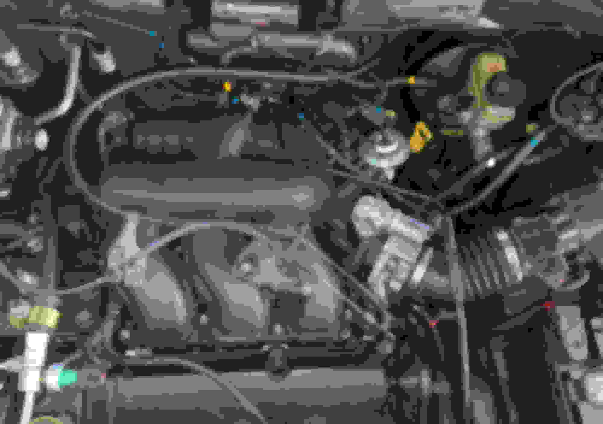
I can pull the air box and battery tomorrow to show you more of the routing from the 03 3.0 Tribute I've got. I took and colored a picture for yuh. It's pretty high-def, so you should be able to zoom in.
The brake booster is straight forward, at least in the engine bay.
There are 4 vac lines on the upper intake manifold/plenum. The right-most and largest in the group of 3 I left uncolored. It runs to the PCV valve underneath the intake manifold and fuel rail. It's annoying, to say the least.
The red line is the transmission vent (which just terminates open on a bracket below the throttle body), the white one runs from the EVAP vapor management valve to the 4th port on the upper intake, just behind the throttle body.
The tricky one is the one I marked blue. It has several T connections. It runs from the cabin to that canister below the computer, has a check valve, to the upper intake, to the EVAP vapor management valve (the little can with 3 hoses off to the driver's side of the engine bay,) to two ports on the EGR vacuum regulator (thing thing right behind the EGR), to the EGR, and terminates finally at the fuel pulse dampener (silver pancake, below throttle body).
EDIT: one note. The blue marked vac lines were glued onto the plastic fittings. If you remove them, make sure a chunk of the glue doesn't get trapped in the hoses or T connectors and cause an obstruction.
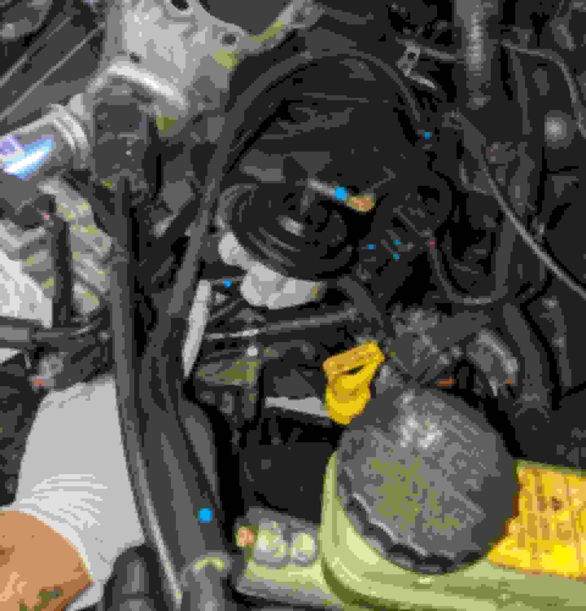
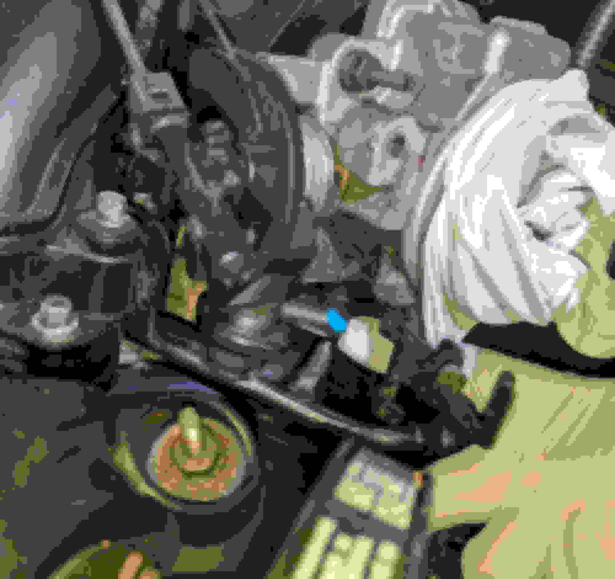
EDIT: added pictures of the rest of the vac line I marked as blue, now showing connection to the EVAP vapor management valve, EGR vacuum regulator, EGR, and finally the fuel pulse dampener.
Apologies for the engine bay looking a mess. Im in the middle of pulling the transmission, so stuff like the shift linkage, ect is in an above image. The blue dot vac lines are unaffected by present work and shown installed just as they would be if the engine was running. I would have taken bigger pictures, but since i'm not tech-savvy I handled the 10mb photo size limit by cropping.
Any chance you could show where the 4th port on the intake is for the white vacuum line from the EVAP? For the like of me I can't find it.
Hopefully I'll get the opportunity to check the vacuum lime tomorrow! The car is coming back for a suspension noise complaint. I've got to say, when this thing is in good health it's a pleasure to drive. The engine is quite peppy, and I loved the turn radius.
Hey, if you're interested I could post up procedures for removing the intake manifold. Doing that would show you pretty much all there is to see.

 12-05-2022, 10:40 AM